Difference between revisions of "Ed Powell"
From WLCS
(→Proposal) |
|||
| (61 intermediate revisions by the same user not shown) | |||
| Line 1: | Line 1: | ||
| − | ''' | + | == '''Proposal''' == |
| − | + | '''Description:''' | |
| + | * A single LED cube will be built using an ATmega 16 to control it | ||
| + | * The ATmega 16 will be programmed with C using AVR Studio and an AVRISP MKII to load the program onto the micro-controller | ||
| + | * The instruction set to program the micro-controller will be learned from the PDFs available on Atmel's website and from other linked websites | ||
| + | * A breadboard will be used to aid in learning the instruction set and to ease programming | ||
| + | ** An ATmega 168 will be used in addition to the ATmega 16 while the instruction set is being learned | ||
| + | |||
| + | |||
| + | '''Progress:''' | ||
| + | * All of the necessary parts to learn the instruction set for the micro-controller and build the cube have been purchased (see list below) - ✓ | ||
| + | * The C Programming website tutorials have been completed and a program for each section has been made - ✓ (click the links below to view) | ||
| + | ** Two sections should be done during each class | ||
| + | ** Sections completed during the last class should be reviewed to ensure that its not forgotten | ||
| + | * Tutorials have been found that explain the programming process sufficiently (links to tutorials will be posted as they're found) - Ongoing | ||
| + | * Start working with the micro-controller understand how it works - ✓ | ||
| + | ** The breadboard should be used so circuits can be made, tested, and then disassembled | ||
| + | ** A blink LED program has been executed - Ongoing | ||
| + | *** Wire the circuit and load the program onto the micro-controller - ✓ | ||
| + | *** Test the circuit and make sure the LED blinks - Needs Debugging | ||
| + | ** Other beginner programs should be made and tested - Ongoing | ||
| + | * All of the necessary parts to build the cube have been purchased (see list below) - ✓ | ||
| + | * All parts have been soldered onto the proto-board and the circuitry has been wired - Ongoing | ||
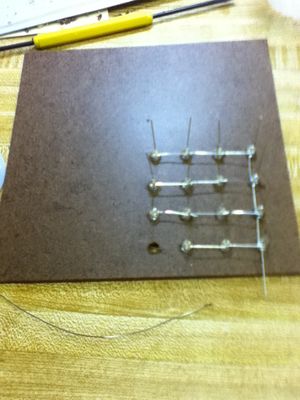
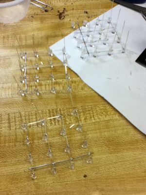
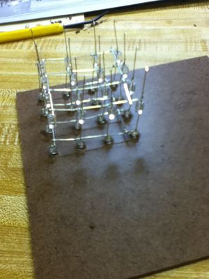
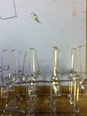
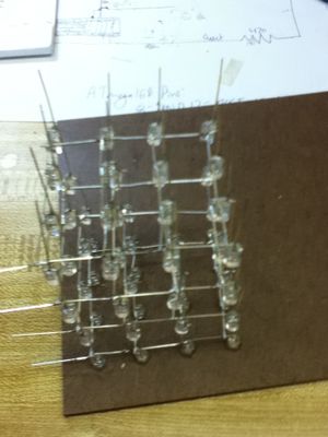
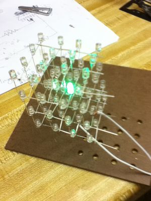
| + | ** The LEDs have been bent, soldered into layers, and and soldered together into their final cubic form (see Pictures 1 to 6) - ✓ | ||
| + | ** The remaining parts have been soldered to the proto-board - ✓ | ||
| + | ** The finished LED cube has been soldered to the proto-board - | ||
| + | ** The circuitry has been wired and the micro-controller is ready to be programmed - | ||
| + | * The programming of the main program has been started - | ||
| + | * The final cube has been tested - | ||
| + | |||
| + | |||
| + | '''Pictures of Progress:''' | ||
| + | {| | ||
| + | |[[File:Cube_Template.jpg|thumb|alt=image 1|Picture 1: Cube Template with an Unfinished Layer]] | ||
| + | |[[File:Cube_Layers.jpg|thumb|alt=image 1|Picture 2: Completed Cube Layers]] | ||
| + | |[[File:Stacked_Layers.jpg|thumb|alt=image 1|Picture 3: Layers of Cube]] | ||
| + | |[[File:Bent_Anodes.jpg|thumb|alt=image 1|Picture 4: Bent Anodes to be Soldered to Form the Cube]] | ||
| + | |[[File:Final_Cube.jpg|thumb|alt=image 1|Picture 5: Completed Cube]] | ||
| + | |[[File:Final_Cube_Test.jpg|thumb|alt=image 1|Picture 6: Test of LEDs in the Final Cube]] | ||
| + | |} | ||
| + | |||
| + | '''Code:''' | ||
| + | * [http://paulbui.net/wiki/images/9/9f/Hello_World.txt Hello World] | ||
| + | * [http://paulbui.net/wiki/images/c/c2/Birthday_Prompt.txt Birthday Prompt] | ||
| + | * [http://paulbui.net/wiki/images/c/c3/Power_3.txt Power of 3] | ||
| + | * [http://paulbui.net/wiki/images/4/4a/Factorial_Sequence.txt Factorial Sequence] | ||
| + | * [http://paulbui.net/wiki/images/4/41/Fibonacci_Sequence.txt Fibonacci Sequence] | ||
| + | * [http://paulbui.net/wiki/images/1/16/MPAA_Calculator.txt MPAA Calculator] | ||
| + | * [http://paulbui.net/wiki/images/a/a6/Print_Square.txt Print Square] | ||
| + | * [http://paulbui.net/wiki/images/f/f0/Print_Triangle.txt Print Triangle] | ||
| + | * [http://paulbui.net/wiki/images/7/79/Print_Initials.txt Print Initials] | ||
| + | |||
| + | |||
| + | '''Parts:''' | ||
| + | * The following parts will be used: | ||
| + | ** [http://parts.digikey.com/1/parts/552059-ic-avr-mcu-16k-16mhz-5v-40dip-atmega16-16pu.html Atmel Atamega16 micro-controller] | ||
| + | ** [http://parts.digikey.com/1/parts/408608-programmer-avr-system-atavrisp2.html Programmer for the micro-controller] | ||
| + | ** [http://www.radioshack.com/product/index.jsp?productId=2102843&filterName=Type&filterValue=Breadboards Proto-board] | ||
| + | ** [http://www.superbrightleds.com/cgi-bin/store/index.cgi?action=DispPage&Page2Disp=/specs/G16120_specs.htm 64 green LEDs] | ||
| + | ** [http://www.superbrightleds.com/cgi-bin/store/index.cgi?action=DispPage&Page2Disp=/specs/R12120_specs.htm 1 red status LED] | ||
| + | ** [http://www.radioshack.com/product/index.jsp?productId=2062317&filterName=Type&filterValue=1%26amp;amp;%23047;2-watt+resistors 16 220 ohm resistors for LEDs] | ||
| + | ** [http://www.radioshack.com/product/index.jsp?productId=2062320&filterName=Type&filterValue=1%26amp;%23047;2-watt+resistors 2 470 ohm resistors] | ||
| + | ** [http://www.radioshack.com/product/index.jsp?productId=2062330&filterName=Type&filterValue=1%26amp;%23047;2-watt+resistors 1 10k resistor] | ||
| + | ** [http://www.radioshack.com/product/index.jsp?productId=2062325&filterName=Type&filterValue=1%26amp;%23047;2-watt+resistors 4 2.2 k resistors] | ||
| + | ** [http://www.radioshack.com/product/index.jsp?productId=2062586&filterName=Type&filterValue=Transistor 4 2N2222 NPN transistors] | ||
| + | ** [http://www.radioshack.com/product/index.jsp?productId=2062365&filterName=Type&filterValue=Ceramic+disc+capacitors 6 0.1uF ceramic capacitors] | ||
| + | ** [http://www.radioshack.com/product/index.jsp?productId=2103610&filterName=Type&numProdsPerPage=60&filterValue=Electrolytic+capacitors 1 10uf capacitor] | ||
| + | ** [http://www.radioshack.com/product/index.jsp?productId=2102507&filterName=Type&filterValue=Electrolytic+capacitors 1 1000uf capacitor] | ||
| + | ** [http://www.sparkfun.com/products/8571 2 22pF ceramic capacitors] | ||
| + | ** [http://www.sparkfun.com/products/669 1 14.7456 MHz crystal] | ||
| + | ** [http://www.radioshack.com/product/index.jsp?productId=3060978 2 tactile buttons] | ||
| + | ** [http://www.radioshack.com/product/index.jsp?productId=2062509 1 power switch] | ||
| + | ** [http://www.radioshack.com/product/index.jsp?productId=2062605 40 pin connector for micro-controller] | ||
| + | ** A spare USB cable (for power) | ||
| + | *** [http://en.wikipedia.org/wiki/Universal_Serial_Bus USB ports provide a constant 5V] | ||
| + | * Unused or Unnecessary Parts: | ||
| + | ** [http://www.radioshack.com/product/index.jsp?productId=2062497 Power switch (being replaced with a spare USB cable)] | ||
| + | |||
| + | |||
| + | '''Links:''' | ||
| + | * Links are added in the order they were found | ||
| + | * [http://www.instructables.com/id/LED-Cube-4x4x4/?images*images 4x4x4 LED Cube Instructable] | ||
| + | * [http://dclausen.net/projects/ledcyl/ RGB LED Cylinder] | ||
| + | * [http://www.thinkgeek.com/gadgets/lights/d71d/?cpg=froogle Think Geek Cube Available to Buy] | ||
| + | * [http://www.lomont.org/Projects/LEDCube/LEDCube4.php RGB LED Cube Story] | ||
| + | * [http://hypnocube.com/ RGB LED Cube Story Cube For Sale] | ||
| + | * [http://www.lumisense.com/?page=eightcubed-v1 8x8x8 RGB LED Cube] | ||
| + | * [http://embeddedmicro.com/ RGB LED Cube Directions] | ||
| + | * [http://hypnocube.com/ RGB LED 4x4x4 Cube Directions] | ||
| + | * [http://popularmicrocontrollers.com/avr-c-tutorial C programming Tutorials] | ||
| + | * [http://ladyada.net/make/minipov3/software.html Installing the Software on the Micro-Controller] | ||
| + | * [http://courses.cit.cornell.edu/ee476/FinalProjects/s2008/pae26_rwc28/pae26_rwc28/index.html#AppendixA 5x5x5 LED Cube Instructable] | ||
| + | * [http://www2.tech.purdue.edu/ecet/courses/referencematerial/atmel/ ATmega16 Programming Guide] | ||
| + | * [http://web.archive.org/web/20040202003107/http://www.microschematic.com/inde.html ATmega Architecture Guide] | ||
| + | * [http://abdullah.0fees.net/atmega32.php ATmega32 Programming Guide] | ||
| + | * [http://www.avrbeginners.net/ AVR Programming Guide] | ||
| + | * [http://www.linuxfocus.org/English/November2004/article352.shtml AVR C Programming Guide] | ||
| + | * [http://www.atmel.com/dyn/resources/prod_documents/doc2466.pdf ATmega 16 Data Sheet | ||
| + | * [http://elasticsheep.com/2009/09/blinking-the-leds/ ATmega 168 Blink LED Tutorial] | ||
| + | * [http://www.atmel.com/dyn/resources/prod_documents/doc2545.pdf ATmega 168 Data Sheet] | ||
| + | * [http://www.instructables.com/id/Ghetto-Programming%3a-Getting-started-with-AVR-micro/step4/Make-Programmer-Cable/ Parallel Port Programmer Cable] | ||
| + | * [http://www.atmel.com/dyn/resources/prod_documents/AVRISPmkII_UG.pdf Data Sheet for AVRISP MKII] | ||
| + | * [http://www.societyofrobots.com/robotforum/index.php?topic=3013.0 AVRISP MKII Help] | ||
| + | |||
| + | |||
| + | ---- | ||
| + | |||
| + | |||
| + | '''Possible Later Goal:''' | ||
| + | * Build an RGB LED cube after the single color cube is finished using the following parts (if deemed possible): | ||
| + | ** Acrylic Case | ||
| + | ** H4C printed circuit board | ||
| + | ** 110VAC to 9VDC 300mA transformer | ||
| + | ** 22 AWG straightened galvanized soft steel wire x40 | ||
| + | ** Diffuse common-cathode RGB LED x64 | ||
| + | ** PIC18F4620 micro-controller (40 pins) | ||
| + | ** SN74AHC574 octal D-type flip-flop x4 (20 pins) | ||
| + | ** ULN2803A NPN Darlington transistor array (18 pins) | ||
| + | ** LM2574 5V switching regulator (8 pins) | ||
| + | ** 22 resistor array (16 pins) | ||
| + | ** 47 resistor array (16 pins) | ||
| + | ** 68 resistor array (16 pins) | ||
| + | ** 47K resistor x3 (yellow-violet-orange-gold) | ||
| + | ** 1K resistor x5 (brown-black-red-gold) | ||
| + | ** 1N4148TR signal diode x24 (red) | ||
| + | ** 511-BAT48 rectifier diode (blue) | ||
| + | ** 330mH inductor | ||
| + | ** 0.1uF ceramic capacitor x5 | ||
| + | ** 10uF electrolytic capacitor | ||
| + | ** 22uF electrolytic capacitor | ||
| + | ** 220uF electrolytic capacitor | ||
| + | ** 6” black wire | ||
| + | ** 18” red wire | ||
| + | ** 24” white wire | ||
| + | ** 2.1mm DC power jack | ||
| + | ** Toggle switch | ||
| + | ** Momentary toggle switch x2 | ||
| + | ** 1” threaded standoff x4 | ||
| + | ** 1⁄2” 4-40 screw x8 | ||
| + | ** Rubber feet x4 | ||
| + | ** DLP-UB232R UART-USB bridge module | ||
| + | ** Mini-B USB cable | ||
Latest revision as of 12:25, 20 June 2011
Proposal
Description:
- A single LED cube will be built using an ATmega 16 to control it
- The ATmega 16 will be programmed with C using AVR Studio and an AVRISP MKII to load the program onto the micro-controller
- The instruction set to program the micro-controller will be learned from the PDFs available on Atmel's website and from other linked websites
- A breadboard will be used to aid in learning the instruction set and to ease programming
- An ATmega 168 will be used in addition to the ATmega 16 while the instruction set is being learned
Progress:
- All of the necessary parts to learn the instruction set for the micro-controller and build the cube have been purchased (see list below) - ✓
- The C Programming website tutorials have been completed and a program for each section has been made - ✓ (click the links below to view)
- Two sections should be done during each class
- Sections completed during the last class should be reviewed to ensure that its not forgotten
- Tutorials have been found that explain the programming process sufficiently (links to tutorials will be posted as they're found) - Ongoing
- Start working with the micro-controller understand how it works - ✓
- The breadboard should be used so circuits can be made, tested, and then disassembled
- A blink LED program has been executed - Ongoing
- Wire the circuit and load the program onto the micro-controller - ✓
- Test the circuit and make sure the LED blinks - Needs Debugging
- Other beginner programs should be made and tested - Ongoing
- All of the necessary parts to build the cube have been purchased (see list below) - ✓
- All parts have been soldered onto the proto-board and the circuitry has been wired - Ongoing
- The LEDs have been bent, soldered into layers, and and soldered together into their final cubic form (see Pictures 1 to 6) - ✓
- The remaining parts have been soldered to the proto-board - ✓
- The finished LED cube has been soldered to the proto-board -
- The circuitry has been wired and the micro-controller is ready to be programmed -
- The programming of the main program has been started -
- The final cube has been tested -
Pictures of Progress:
Code:
- Hello World
- Birthday Prompt
- Power of 3
- Factorial Sequence
- Fibonacci Sequence
- MPAA Calculator
- Print Square
- Print Triangle
- Print Initials
Parts:
- The following parts will be used:
- Atmel Atamega16 micro-controller
- Programmer for the micro-controller
- Proto-board
- 64 green LEDs
- 1 red status LED
- 16 220 ohm resistors for LEDs
- 2 470 ohm resistors
- 1 10k resistor
- 4 2.2 k resistors
- 4 2N2222 NPN transistors
- 6 0.1uF ceramic capacitors
- 1 10uf capacitor
- 1 1000uf capacitor
- 2 22pF ceramic capacitors
- 1 14.7456 MHz crystal
- 2 tactile buttons
- 1 power switch
- 40 pin connector for micro-controller
- A spare USB cable (for power)
- Unused or Unnecessary Parts:
Links:
- Links are added in the order they were found
- 4x4x4 LED Cube Instructable
- RGB LED Cylinder
- Think Geek Cube Available to Buy
- RGB LED Cube Story
- RGB LED Cube Story Cube For Sale
- 8x8x8 RGB LED Cube
- RGB LED Cube Directions
- RGB LED 4x4x4 Cube Directions
- C programming Tutorials
- Installing the Software on the Micro-Controller
- 5x5x5 LED Cube Instructable
- ATmega16 Programming Guide
- ATmega Architecture Guide
- ATmega32 Programming Guide
- AVR Programming Guide
- AVR C Programming Guide
- [http://www.atmel.com/dyn/resources/prod_documents/doc2466.pdf ATmega 16 Data Sheet
- ATmega 168 Blink LED Tutorial
- ATmega 168 Data Sheet
- Parallel Port Programmer Cable
- Data Sheet for AVRISP MKII
- AVRISP MKII Help
Possible Later Goal:
- Build an RGB LED cube after the single color cube is finished using the following parts (if deemed possible):
- Acrylic Case
- H4C printed circuit board
- 110VAC to 9VDC 300mA transformer
- 22 AWG straightened galvanized soft steel wire x40
- Diffuse common-cathode RGB LED x64
- PIC18F4620 micro-controller (40 pins)
- SN74AHC574 octal D-type flip-flop x4 (20 pins)
- ULN2803A NPN Darlington transistor array (18 pins)
- LM2574 5V switching regulator (8 pins)
- 22 resistor array (16 pins)
- 47 resistor array (16 pins)
- 68 resistor array (16 pins)
- 47K resistor x3 (yellow-violet-orange-gold)
- 1K resistor x5 (brown-black-red-gold)
- 1N4148TR signal diode x24 (red)
- 511-BAT48 rectifier diode (blue)
- 330mH inductor
- 0.1uF ceramic capacitor x5
- 10uF electrolytic capacitor
- 22uF electrolytic capacitor
- 220uF electrolytic capacitor
- 6” black wire
- 18” red wire
- 24” white wire
- 2.1mm DC power jack
- Toggle switch
- Momentary toggle switch x2
- 1” threaded standoff x4
- 1⁄2” 4-40 screw x8
- Rubber feet x4
- DLP-UB232R UART-USB bridge module
- Mini-B USB cable
